FLYNC Examples
Welcome to the configuration examples and tutorials! This section walks you through practical usage of the FLYNC configuration system with real examples.
Base Example
This example provides a fully functional reference configuration that can be used as a baseline when developing your own system setup. It demonstrates how multiple networking features can be integrated into a cohesive design, helping you understand both structure and implementation details.
The configuration includes the following key components:
Ethernet Network Topology - Illustrates how devices are interconnected, including port roles, link relationships, and overall network structure. This serves as a guide for designing scalable and deterministic Ethernet architectures.
Time Synchronization - Shows how gPTP configuration is defined and maintained across the network.
MACsec - Shows the configuration of MACsec-aware nodes of the system for link protection.
Quality of Service (QoS), Layer 2 TSN, and TCAM Usage - Provides sample configurations for traffic prioritization and deterministic networking using Time-Sensitive Networking (TSN) features. It also illustrates how TCAM rules can be allocated and used for traffic classification and filtering. You can use this configuration as a starting point, adapting interface mappings, policies, and feature parameters to match the specific requirements of your hardware platform and application.
Network Management (NM) - Shows how an NM message is modelled vendor-agnostic as an ordinary PDU with ordinary signals, tagged via the
pdu_usage/frame_usagefields, and bound to both Ethernet and CAN transports.
Example Configuration
Find an example configuration directly in github.
Ethernet Network Topology
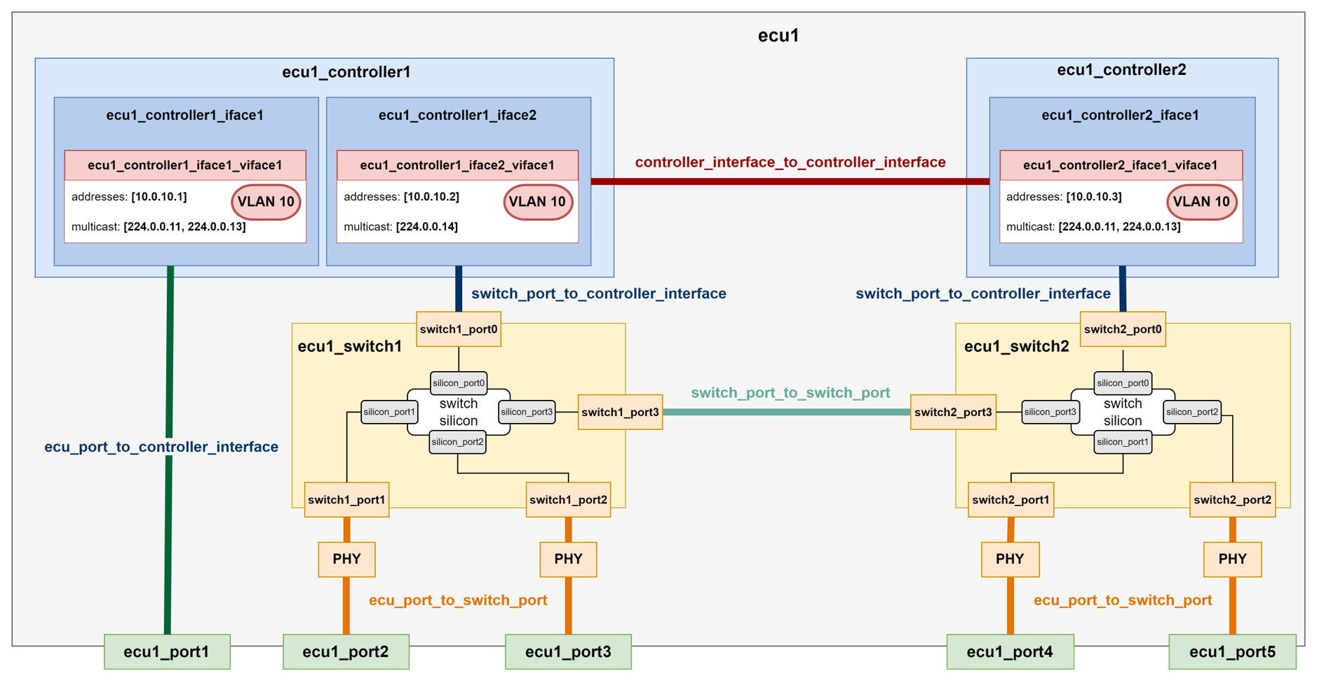
The Ethernet Network Topology diagram provides a comprehensive visual representation of all components included in the configuration.
The diagram identifies the VLANs, IP addresses, and multicast groups assigned to each controller and switch, giving a complete view of the logical network segmentation and addressing scheme.
Each of the four ECUs is shown as an individual block. The diagram also illustrates the internal connectivity between components within each ECU, as well as the external connections between ECUs, making both intra-ECU and inter-ECU communication paths easy to understand.

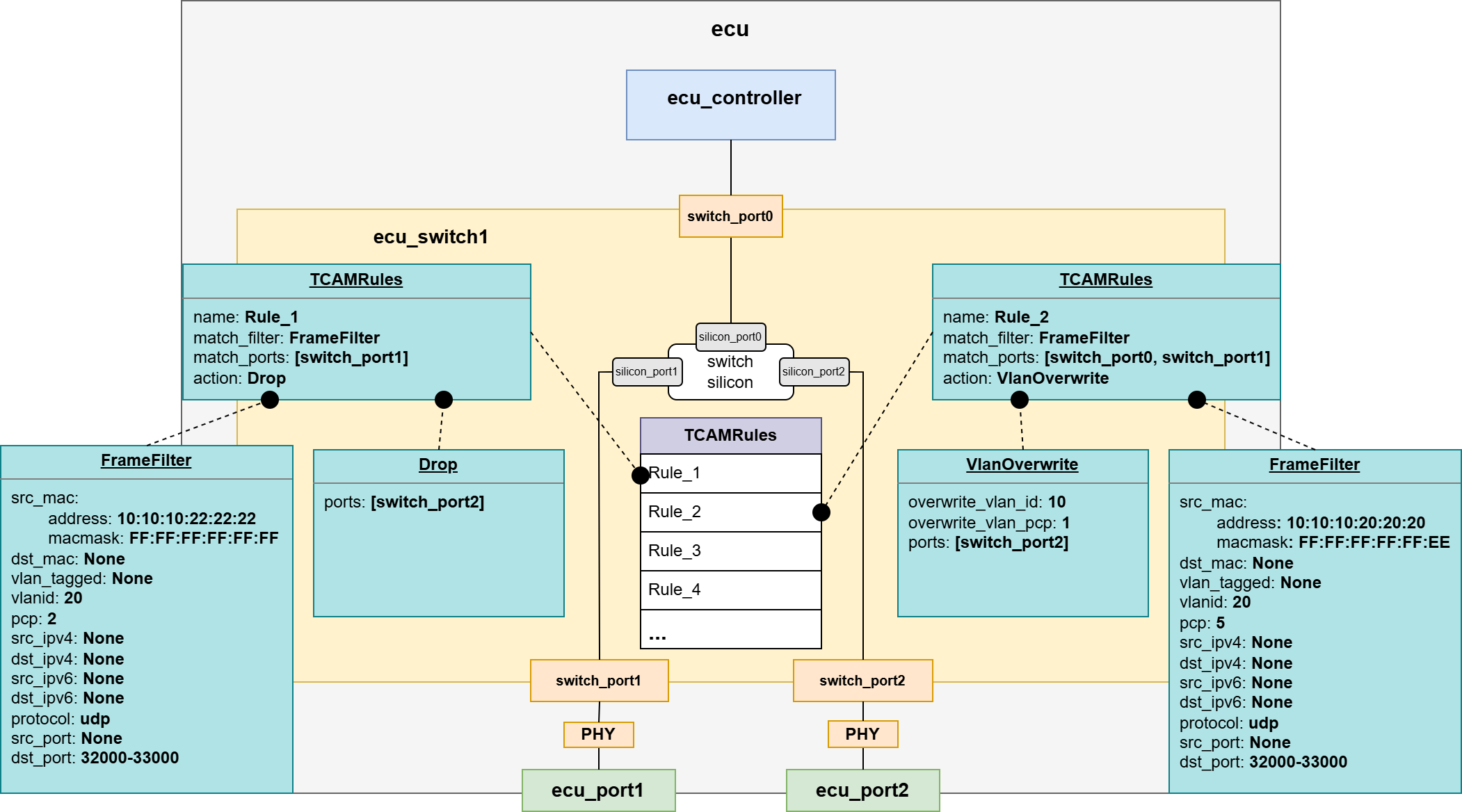
QoS/L2 TSN and TCAM Configuration
The QoS / Layer 2 TSN and TCAM Configuration diagram provides a comprehensive visual overview of the Time-Sensitive Networking (TSN) mechanisms and TCAM rules implemented in this configuration.
The diagram highlights the HTB (Hierarchical Token Bucket) shaper configured on the Linux-based controllers (eth_ecu), as well as the Credit-Based Shapers (CBS) applied on the egress ports of the switches to manage time-sensitive traffic.
It also shows the ingress stream filters deployed on the ingress ports of the switches, which are used for traffic policing and stream identification in accordance with TSN requirements.
In addition, the diagram includes the TCAM rules configured on the switch (z2_switch1), illustrating how hardware-based classification and filtering are used to enforce traffic handling policies.

Time Synchronization Configuration
The Timesync Configuration diagram provides a clear visual overview of the time-synchronization roles assigned to all time-aware devices in the system.
It illustrates how time is distributed across the network, identifying which devices act as time-transmitters or time_receivers.
This helps clarify the synchronization hierarchy and the timing relationships between system components.

MACsec Configuration
The MACsec Configuration diagram provides a clear visual overview of the roles and relationships of all MACsec participants within the system.
It identifies which devices function as MACsec peers, showing where secure channels are established and how link-layer protection is applied across the network.
This helps clarify the security topology and illustrates how data integrity (and confidentiality) is maintained between connected nodes.

Further Examples
ECU Variants
Variant 1: Single controller, single (virtual) interface, external PHY
Find this example on github: ecu_variant_1.

Note
The MDI configuration must be compliant with that of the other ECU to which the port is connected to. In this case, mode, speed and duplex must match; while role must be opposite to that of the other ECU config (i.e., if slave in the connected ECU, master shall be configured).
Note
The MII configuration must be compliant with that of the ECU controller configuration. In this case, type and speed must match; while mode must oppose the controller interface config (i.e., if mac in the controller interface, phy shall be configured).
Variant 2: Single controller, single (virtual) interface, integrated PHY
Find this example on github: ecu_variant_2.

Note
Since PHY is integrated into the host controller, no MII configuration is needed neither on the port side, nor on the controller side.
Variant 3: Single controller, multiple (virtual) interfaces, external PHY
Find this example on github: ecu_variant_3.

Variant 4: Single controller, multiple (virtual) interfaces, integrated PHY
Find this example on github: ecu_variant_4.

Variant 5: Single controller, single (physical) interface, external PHY, Multiple VMs
Find this example on github: ecu_variant_5.

Note
If there is a VM, it needs to tie to a Controller Interface through a Virtual Switch.
Variant 6: Single controller, multiple (physical) interface, external PHY no VMs, Virtual Switch
Find this example on github: ecu_variant_6.

Note
Two controller interfaces might be connected through an Virtual Switch.
Variant 7: Switch ECU, multiple (virtual) interfaces, external PHY
Find this example on github: ecu_variant_7.

Note
The MII mode of the switch1_port0 must oppose the one of the ecu1_controller1_iface1.
Variant 8: Switch ECU with Host controller, multiple (virtual) interfaces, external PHY
Find this example on github: ecu_variant_8.

Note
The MII mode of the switch1_port0 must oppose the one of the ecu1_controller1_iface1.
Note
The Host controller of the switch will have the same configuration as any Controller Interface.
Internal Topology (Configuration and Types)
The internal topology file of each configured ECU must contain the description of all the internal connections within the device. The FLYNC model supports the connection types present in the following picture:
Important
Be aware of the kind of connection that is added to the file, since the name of the components shall adjust to it accordingly.
Example file (dummy example)
📄 ecu1_internal_topology.flync.yaml
connections:
   -  type: ecu_port_to_switch_port
      id: conn1
      ecu_port: ecu1_port2
      switch_port: switch1_port1
   -  type: ecu_port_to_switch_port
      id: conn2
      ecu_port: ecu1_port3
      switch_port: switch1_port2
   -  type: ecu_port_to_switch_port
      id: conn3
      ecu_port: ecu1_port4
      switch_port: switch2_port1
   -  type: ecu_port_to_switch_port
      id: conn4
      ecu_port: ecu1_port5
      switch_port: switch2_port2
   -  type: ecu_port_to_controller_interface
      id: conn5
      ecu_port: ecu1_port1
      controller_interface: ecu1_controller1_iface1
   -  type: switch_port_to_controller_interface
      id: conn6
      switch_port: switch1_port0
      controller_interface: ecu1_controller1_iface2
   -  type: switch_port_to_controller_interface
      id: conn7
      switch_port: switch2_port0
      controller_interface: ecu1_controller2_iface1
   -  type: controller_interface_to_controller_interface
      id: conn8
      controller_interface: ecu1_controller1_iface2
      controller_interface2: ecu1_controller2_iface1
   -  type: switch_port_to_switch_port
      id: conn9
      switch_port: switch1_port3
      switch2_port: switch2_port3
Additional Security Features Configuration
Firewall Configuration
The Firewall model consists of a default action and three lists defining rules for input, output and forward traffic, respectively. Each of these rules contains a pattern the packets are matched against, and an action executed when this check is positive:
📄 ecu1_controller1.flync.yaml
meta:
   author: Developer1
   compatible_flync_version:
      version_schema: semver
      version: 0.11.0
name: ecu1_controller1
interfaces:
   -  name: ecu1_controller1_iface1
      mac_address: 00:11:22:33:44:88
      mii_config:
      type: rmii
      speed: 100
      mode: mac
      virtual_interfaces:
      -  name: ecu1_controller1_iface1_viface1
         vlanid: 0
         addresses:
            -  address: 10.0.10.3
               ipv4_netmask: 255.255.255.0
      firewall:
         default_action: drop
         input_rules:
            -  name: allow_ssh
               action: accept
               pattern:
               src_ipv4: 10.0.0.2
               protocol: tcp
               dst_port: 22
               vlan_tagged: true
         output_rules:
            -  name: drop_output_vlan_33
               action: drop
               pattern:
               dst_ipv4:
                  address: 10.0.0.1
                  ipv4netmask : 255.255.255.0
               vlanid: 33
         forward_rules:
            -  name: allow_forwarded_udp
               action: accept
               pattern:
               src_ipv4:
                  address: 10.0.0.2
                  ipv4netmask : 255.255.255.0
               dst_ipv4:
                  address: 10.0.0.3
                  ipv4netmask : 255.255.255.0
               protocol: udp
               dst_port:
                     from_value: 30490
                     to_value: 30509
Switch TCAM Configuration
📄 ecu1_switch1.flync.yaml
meta:
   author: Developer1
   compatible_flync_version:
      version_schema: semver
      version: 0.11.0
name: ecu_switch1
ports:
-  name: switch_port0
   silicon_port_no: 1
   default_vlan_id: 1
   mii_config:
      type: rmii
      speed: 100
      mode: mac

-  name: switch_port1
   silicon_port_no: 2
   default_vlan_id: 1
   mii_config:
      type: rmii
      speed: 100
      mode: mac

-  name: switch_port2
   silicon_port_no: 3
   default_vlan_id: 1
   mii_config:
      type: rmii
      speed: 100
      mode: mac

tcam_rules:
   -  name: Rule_1
      match_filter:
      src_mac:
         address: "10:10:10:22:22:22"
         macmask: "FF:FF:FF:FF:FF:FF"
      vlanid: 20
      pcp: 2
      protocol: udp
      dst_port:
         from_value: 32000
         to_value: 33000
      match_ports: [switch_port1]
      action:
      -  type: drop
         ports: [switch_port2]

   -  name: Rule_2
      match_filter:
      src_mac:
         address: "10:10:10:20:20:20"
         macmask: "FF:FF:FF:FF:FF:EE"
      vlanid: 20
      pcp: 5
      protocol: udp
      dst_port:
         from_value: 32000
         to_value: 33000
      match_ports: [switch_port0, switch_port1]
      action:
         -  type: vlan_overwrite
            overwrite_vlan_id: 10
            overwrite_vlan_pcp: 1
            ports: [switch_port2]

vlans:
-  name: VLAN10
   id: 10
   default_priority: 1
   ports:
      - switch_port0
      - switch_port1
      - switch_port2

-  name: VLAN20
   id: 20
   default_priority: 1
   ports:
      - switch_port0
      - switch_port1
      - switch_port2
Sockets Configuration
A socket in FLYNC represents a logical endpoint on a virtual network interface of an ECU. It defines how the controller will send and receive traffic over a specific IP address, port, and protocol (TCP/UDP).

Note
Sockets must be defined in a separate folder for each ECU for better readability.
Note
Multiple sockets may be defined in a single file for different address endpoints, but they must belong to the same VLAN.
Network Management (NM)
The example illustrates a vendor-agnostic Network Management configuration that exercises both Ethernet and CAN transports with a single PDU definition.
The NM message is modelled as an ordinary PDU (PDU_NmMessage) with ordinary signals:
sender_id(uint8) - identifies the sending node.relevance_vector(uint8) - a partial-network relevance bitmask. The bit-to-function mapping uses thebitmask_flagsvalue encoding, so each bit carries a named label (MirrorLeft,MirrorRight,CabinLight,EngineStatus,TransmissionStatus,VehicleDynamics) that matches a real application PDU in this workspace.user_data(bytearray, 6 bytes) - opaque OEM/application extension area.
The PDU is flagged pdu_usage: network_management, so any tool processing the catalog can recognize it as the NM message regardless of which transport carries it.
Ethernet NM
This example NM PDU (PDU_NmMessage) is wrapped in an Ethernet Container PDU (eth_nm_container_a) and bound to a UDP socket via the pdu_sender / pdu_receiver deployment types:
Sender -
high_performance_computetransmits the NM container multicast on VLAN 40, group224.0.0.1, UDP port 1200 (its existingnetwork_management_socket).Receivers -
zonal_platform1andzonal_platform2subscribe viapdu_receiversockets on the same VLAN and multicast group.
As an alternative way, the NM PDU (PDU_NmMessage) can be attached to a Ethernet Container PDU (available as example eth_nm_container_b) which does not carry a PDU Header, as header/id_length_bits & length_field_bits are configured with length zero (0), to be sent as a raw UDP payload as example Use-Case.
CAN NM
On the CAN side, the same PDU is carried by Frame_NmMessage on the DiagCAN bus, tagged frame_usage: network_management. The frame is bound to high_performance_compute as a sender_frames entry. high_performance_compute is the only ECU connected to DiagCAN in this workspace, so no receiver_frames entry exists; in a multi-ECU CAN setup, peer ECUs would add Frame_NmMessage under receiver_frames on their own DiagCAN interface — mirroring the Ethernet pdu_receiver pattern.